Extending your map styling with geometry transformations
When designing a map, sometimes you want to render something that is related to the geometries you have at hand, but which is not specifically the geometries themselves. Maybe you want to highlight the end of a line, create a drop shadow effect, or make the vertices that make up a geometry more evident to the user. Unfortunately the SLD specification that GeoServer uses for its rendering does not allow you to dynamically extract such information. If you need to achieve those effects, you will usually need to generate a new layer by preprocessing your data offline (for example, using PostGIS’s excellent spatial analysis functions).
Today I’m going to show you how to achieve those effects dynamically using what we call geometry transformations. Geometry transformations are yet another extension to SLD in order to make it more powerful. (Another example of SLD an extension that GeoServer has implemented is dynamic symbolizers.) Standard SLD allows the user to specify a <Geometry> element in each symbolizer, but its contents can only be a <PropertyName>; this allows a user to choose a different geometry should a spatial table contain more than one. With geometry transformations, GeoServer allows you to specify a filter function as well, which can transform the geometry. (You may want to refer to my previous post on filter functions.)
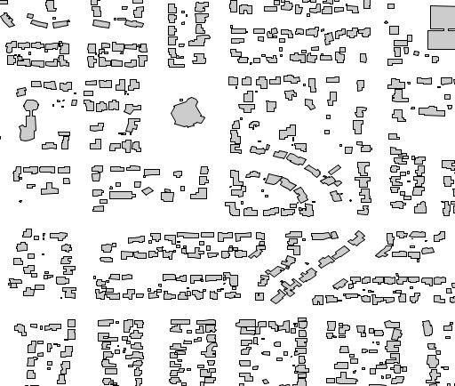
Let’s look at an example. Say we have a building layer, rendered with a plain gray fill:
We can add a twist to this plain map by adding a drop shadow beneath the buildings layer. To achieve this we will offset the buildings a bit, fill them dark gray, and then paint the standard buildings layer on top of it. The style looks like:
      <FeatureTypeStyle>
        <Rule>
          <Title>Shadow</Title>
          <PolygonSymbolizer>
            <Geometry>
               <ogc:Function name="offset">
                  <ogc:PropertyName>the_geom</ogc:PropertyName>
                  <ogc:Literal>0.00004</ogc:Literal>
                  <ogc:Literal>-0.00004</ogc:Literal>
               </ogc:Function>
            </Geometry>
            <Fill>
              <CssParameter name="fill">#555555</CssParameter>
            </Fill>
          </PolygonSymbolizer>
        </Rule>
      </FeatureTypeStyle>
      <FeatureTypeStyle>
        <Rule>
          <Title>Polygon</Title>
          <PolygonSymbolizer>
            <Fill>
              <CssParameter name="fill">#CCCCCC</CssParameter>
            </Fill>
            <Stroke>
              <CssParameter name="stroke">#000000</CssParameter>
              <CssParameter name="stroke-width">0.5</CssParameter>
            </Stroke>
          </PolygonSymbolizer>
        </Rule>
      </FeatureTypeStyle>
And the result is:
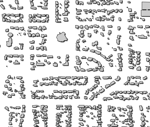
The filter function takes the geometries and offsets them by (0.00004, -0.00004). Geometry transformations occur against the original geometry, which in this particular case is in EPSG:4326, so the values of the offset are also in units of lon/lat.
You can find more examples about this functionality in the geometry transformations section of the User Manual. You can also get creative by looking at the currently available set of filter functions. Also remember, if you want a function that’s not there, it is possible to add new ones; drop by on the developer mailing list and we’ll provide you with directions.